
Create a fixture definition
Build or edit a fixture definition in the Fixture Editor, including its modes, channels, and pixels.
When a fixture is missing from the built-in library, or you built a custom rig by hand, you author its definition in the Fixture Editor. You patch the finished definition into a show in a separate step. Patch a fixture covers that step, and Fixtures and patching explains what definitions, modes, and pixels are.
Start a fixture
Choose Project > Fixture Editor.
The start sheet has three ways in:
- Blank opens one empty mode. You add channels and pixels as you go.
- LED Builder generates a block of pixels with their color roles in one step. Most pixel-mapped fixtures start here, and the next step covers it.
- Find a fixture searches your library. When you switch the picker to GDTF Share, it searches GDTF Share, as described in Add a fixture. What opens depends on the source of the fixture:
- A user fixture opens for editing.
- A built-in fixture opens read-only with a Built-in badge until you click Duplicate to edit. This makes a copy named after the original with "(custom)" added, and gives the copy a new ID.
- A GDTF Share revision that your library lacks opens after you click Import. It opens as a new fixture that is not saved yet. A strip above the editor names the revision and counts what the conversion dropped or adapted. Save puts the fixture in your library.
Build pixels with the LED Builder
The LED Builder opens in its own window. You open it from the start sheet or, inside a mode, from Add pixels…. Work through its settings from top to bottom:
- Choose a Shape: Line, Grid, Ring, or Cube. A line takes an axis. A grid or ring takes a plane: XY faces the front, XZ lies flat, YZ faces the side.
- Set Pixels. A grid takes Width and Height, and a cube takes a Size.
- For a grid, set the Wiring as seen from the front of the fixture:
- the corner of the first pixel
- the direction of the data, along rows or along columns
- the direction of each line, the Same way or turned back as a Snake
- Pick the Colors. Presets such as RGB, RGBW, and RGBWAUV set them in one click. You can also toggle any color role individually.
- Set the Color order to match the LED chips, which often run GRB or GRBW instead of RGB. Click a preset such as GRBW or BGRW, or drag the color chips into place. To move a chip with the keyboard, focus it and press
Enterto pick it up. Move it with the arrow keys, and pressEnteragain to drop it. When the chips wrap,↑and↓move a chip one line at a time. - Set Depth to 8-bit or 16-bit. At 16 bits, every role gets a fine channel right after its coarse one.
- Choose the Grouping. By pixel keeps each pixel's colors together: G1 R1 B1 G2 R2 B2 for a GRB strip. By color runs every pixel's first color, then every pixel's second: G1 G2 G3 and so on, then R1 R2 R3.
The builder spaces the pixels for you, so a new block spans the width of the fixture. When you add pixels to a mode that already has some, the builder starts from the colors, color order, depth, and grouping of the existing pixels. The new pixels match their spacing and sit beside them.
The footer shows how many channels and pixels the build creates. A line of 16 RGBW pixels comes to 64 channels. Click Build, and the 3D view frames the result. To close the window without a build, press Esc.
The LED Builder makes pixels only. Add a dimmer, a strobe, pan and tilt, or zoom afterwards with Add parameter in the channel table.
Find your way around
The left column lists the fixture's modes, the selectable DMX personalities that a fixture offers. Every mode has its own channels, pixels, and parameters, so when you switch modes, everything to the right changes.
- To rename a mode, double-click it or press
Enteron it. - Right-click a mode for Rename, Duplicate, Make default, and Delete.
- To add a mode, click the Mode button at the bottom.
The middle column is the channel table, where most of the work happens. The right column holds the 3D view above the Inspector. When you select a row in the table, the 3D view selects its pixel. When you select pixels in the 3D view, the table selects their rows.
Edit the name, manufacturer, and ID in the header. For a new fixture, the ID follows the name. You can edit the ID until the first save. After that, the ID cannot change, because projects refer to the fixture by its ID. Every edit is one undo step, and a burst of typing in one field counts as one.
Work in the channel table
The table lists every DMX channel of the mode, numbered from 1 to match fixture manuals. The patch decides where channel 1 lands on the wire. Drives shows what each channel controls.
A row marked Unassigned is a reserved or unused channel. Manuals leave gaps, so the table allows gaps. To give one a job, select the row. Then press Enter, double-click the row, click Assign…, or start typing. The assign picker lists pixel roles and parameters that match what you type, and its last entry creates a new parameter with that name. The table flags a pixel with no color role at all, because that pixel can never light.
Some library definitions map one channel to several targets. Such a row shows as Shared and lists everything it drives. In a mode you add yourself, two targets on one channel block saving.
Insert above, Delete, Add pixels…, and Add parameter act at the selection. The table renumbers later channels to make room or to close the gap. Add pixels… opens the LED Builder and adds its pixels at the selected channel. Add parameter offers Dimmer, Dimmer 16-bit, Strobe, Pan / Tilt 16-bit, and Zoom, or a custom name.
To reorder rows, drag a row by its grip. You can also press Option+↑ and Option+↓ to move the selected rows. A 16-bit pair travels together.
Select several rows with Shift+click for a range or Cmd+click to pick individually. A bar of bulk actions appears with them. Make fine turns each selected channel into the fine byte of the channel above it. That control then becomes 16-bit. Move to pixel… moves the selected color roles to another pixel by number. Duplicate pixels appends copies.
A mode with several parts or several DMX breaks, as in some imported fixtures, lets you reassign channels but not insert, delete, or move them.
Place pixels in the 3D view
Drag to orbit, Option-drag to pan, and scroll to zoom. Click a pixel to select it and Cmd-click or Shift-click to add or remove one. Shift-drag draws a box that selects the pixels inside it, and Cmd+Shift-drag adds them to the selection. The mouse and keys work as in the Layout Editor.
The Channels toggle labels each pixel with its first channel. Above 1,024 pixels, the toggle labels only the selection.
The grid box is the fixture's own unit cube, one fixture width on each side, drawn as in the Layout Editor. Grid cells sets how many cells divide each edge. Floor, on by default, draws an endless floor under the grid box. Snap is off by default and makes moves land on half a cell. Rotation and scale never snap.
Behind the pixels the view draws the fixture's body at rest, as the Layout Editor, 3D Aim and the Preview will draw this definition. Spectralite picks the kind of body from the mode's heads, pixels and beams and from the fixture's name, so a row of pixels with no head draws as an LED bar and a mode with pan and tilt as a moving head. Each edit updates it. The body is scaled so the pixels sit on the cells it draws, and a fixture whose definition states no size draws at the typical size of its kind. The pixels, head axes and gizmo always draw in front of it. Pick Silhouettes or Plot Symbols from the toolbar to switch the drawing; it is the same setting as Window > Fixtures, so every view follows. In a mode whose parts are separate bars, the view draws the one bar you edit.
Fine-tune in the Inspector
With one pixel selected, the Inspector shows the Position as X, Y, and Z in fixture widths and a channel field for each color role. Type a new channel number into a role to move it. If another assignment already holds that channel, the two swap places. A field refuses a number outside the mode or a channel that is shared. Set roles… previews how many channels a change adds or frees before you apply it.
With several pixels selected, positions that differ read Mixed. If you type a value, it applies to all of them. Align X, Align Y, and Align Z move the pixels to their average on that axis. Distribute spaces three or more pixels evenly between the outermost two. Reverse channel order gives the last pixel the first pixel's channels, and so on. This fixes a strip wired the wrong way around.
Color order… fixes one or many pixels whose colors are wired in a different order. Pick the order as you would in the LED Builder, then click Apply. Each pixel keeps its own channels, and its colors swap places among them. Fine channels move with their coarse ones. The selected pixels must have the same colors. Each pixel's channels must sit together and drive nothing else.
Select a parameter's row to edit the parameter:
- Group puts it in a feature group such as Dimmer, Position, Color, Beam, or Gobo. When the name suggests a different group, a button offers it.
- Coarse and, for a 16-bit control, Fine set its channels.
- Ranges name bands of values, such as a gobo wheel's slots or a shutter's open and strobe zones, with their start and end DMX values. When every range of a 16-bit control ends at or below 255, the ranges count in coarse values, from 0 to 255. The ranges of a zoom that a beam uses, and of every parameter in the Position group, also take the angles they span (see the next step). A color temperature parameter imported with Kelvin values shows them on its ranges.
- Wheel colors appears for a color parameter. It lists the color that each wheel slot shows, at the coarse-byte value (0 to 255) where its range starts. An effect can import this list as a color map.
Describe heads and beams
A head is a part of the fixture that pans or tilts: the yoke of a moving head, a scanner's mirror, one lamp on a bar. A beam is where light leaves the fixture, and the Preview draws it as light that turns with its head. Both belong to the mode. So when no row is selected, the Inspector lists Heads and then Beams.
Start with the pan and tilt angles, because a head turns by them.
- Add Pan / Tilt 16-bit from Add parameter.
- Select the Pan row.
- In its Angle fields, enter the range from the manual, with 0° at the pose that the head rests in. For example, a 540° pan reads -270 to 270.
- Do the same for Tilt.
Every parameter in the Position group shows these fields.

Then click Head. Spectralite builds the first head from the channel list:
- a yoke that hangs face down
- pan as its outer axis and tilt as its inner one
- a turn about the middle of its pixels
- every channel except pan and tilt on the head
- one beam for each pixel
If the angles are missing, Spectralite adds nothing, and a note names the parameters that still need angles.
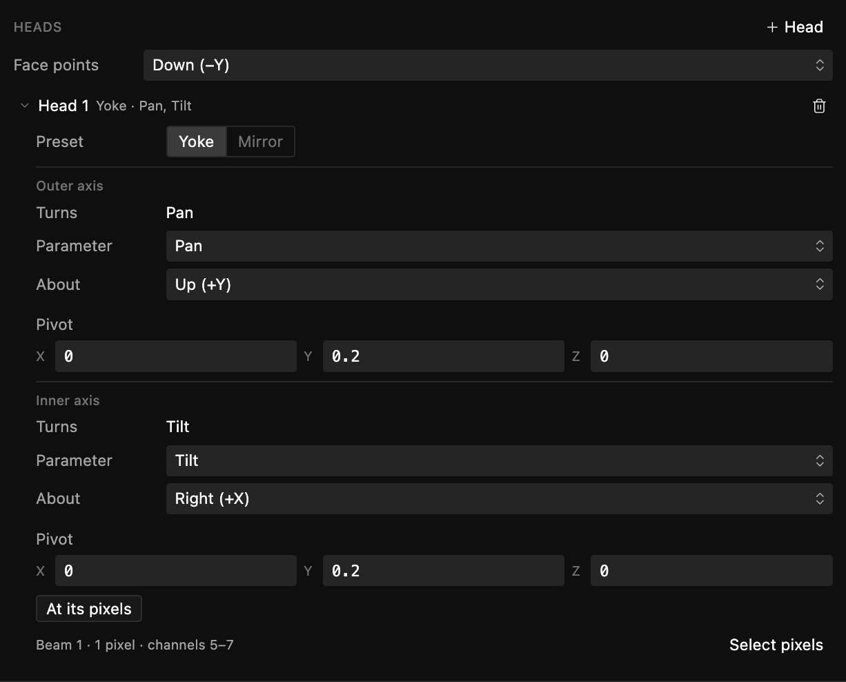
Open a head to edit it:
- Preset picks Yoke, a hung moving head whose beams rest down, or Mirror, a scanner whose beam leaves the mirror toward the audience. Both turn pan about the vertical and tilt about the horizontal. A head with another configuration reads Custom.
- Each axis has the parameter it Turns with and the direction it turns About. It also has a Pivot: a point on the axis line, in fixture widths from the fixture's center. A head with one axis has only an outer one.
- At its pixels puts both pivots at the center of the head's pixels. The line below names what the head carries, and Select pixels selects them.
Face points says where the fixture's face looks when the head is at rest. A hung yoke faces down. When the first beam on a head rests another way, a note offers to point the face that way.
The 3D view draws each head's axes through its pivot. The outer axis is solid and the inner one is dashed. The head's number sits at the point that the head turns about.
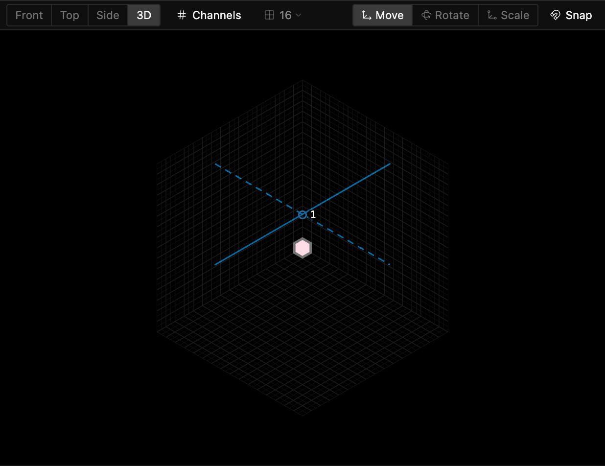
To make the face swing as the real one does, move the tilt pivot behind the face. A tilt axis d behind a face w wide sits at Z = -d / w fixture widths. For example, a 350 mm face with its tilt axis 86 mm behind it puts the pivot at Z -0.25.
What a head carries decides what moves with it. To put something on a head, select a pixel, several pixels, or a parameter. Then pick a head in its Head field. To take it off every head, pick None. Pan and tilt themselves are never on a head. Their row says which head they turn, and if they landed on a head, Take off heads removes them from it.
For a bar of lamps that tilt together and pan one by one, make one head per lamp. Each head turns with the same tilt and carries its own lamp's channels. On a mode that already has heads, Head adds a copy of the last head with nothing on it. You can then move the copy along the bar.
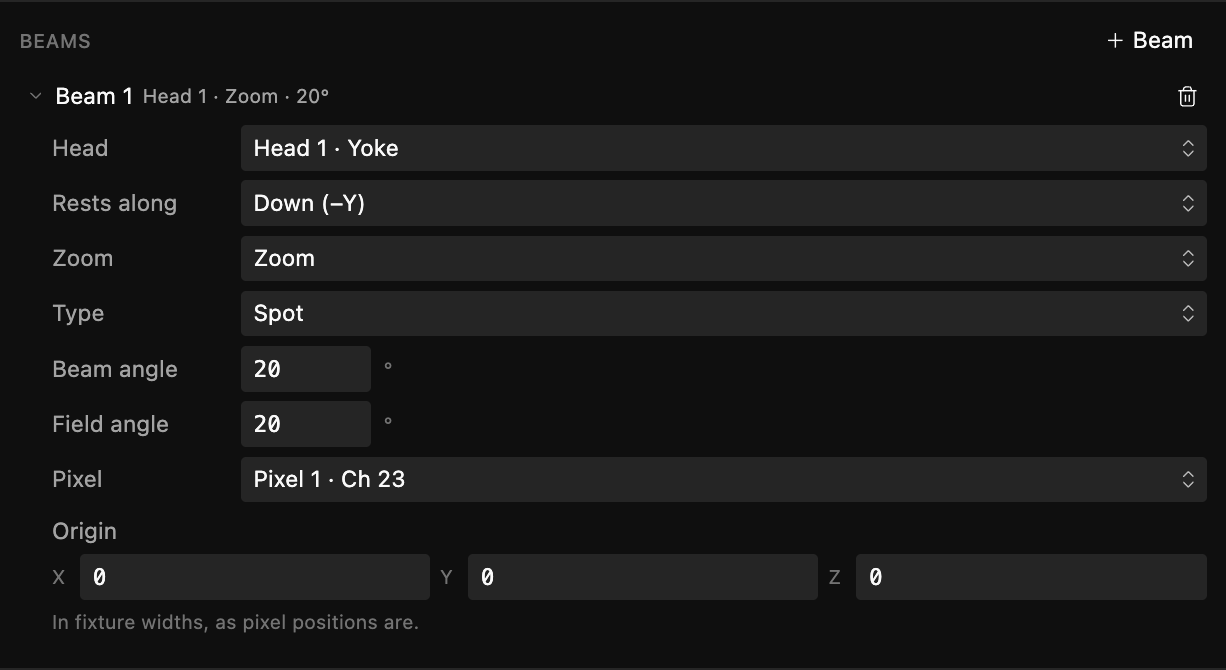
Each beam has these settings:
- Head: the head that turns the beam
- Rests along: the way the beam rests
- Zoom: the zoom parameter, if the fixture has one
- Type
- Beam angle and Field angle
- Pixel: the pixel that its light and color come from
- Origin
When you choose a pixel, the beam's origin moves there, and the beam goes on the head that carries that pixel. When a fixture splits its zoom over two 8-bit parameters, choose the high byte, then its Fine parameter. Beam adds a beam at the next pixel.
The Preview sizes a beam by the angles on the ranges of its zoom. You enter them the same way as pan and tilt: the beam's full width at the range's first value and at its last. For a fixture without zoom, Beam angle is the width where the light falls to half. Field angle is the wider angle where the light fades out, as a datasheet prints it. If your datasheet does not print it, leave it empty. It cannot be narrower than the beam angle.
Type decides how the Preview draws the beam. Spot is a shaft of light, for a spot, profile or beam fixture. PC and Fresnel are soft-edged spots. Wash spreads soft light, and the Preview draws the washes of one head that point the same way as one volume.
Glow and None draw no beam. Use them for an LED ring or other emitter whose own pixels are the light. If you leave Type at From angle, a beam up to 40° is a spot and a wider one is a wash. The select shows which type applies.
Until every zoom that a beam uses has its angles, the warning at the bottom of the channel table blocks Save. The warning takes you to the range that needs angles. A beam or field angle outside 0 to 360°, or a field angle below the beam angle, blocks Save too.
Save the definition
Save, or Cmd+S, writes the fixture to your library under its ID. Every project can then use it.
A fixture needs a name, a manufacturer, and an ID that no other library fixture uses. Each mode needs at least one pixel or parameter. A pixel or parameter must not sit on a channel that another one holds.
Every zoom that a beam uses, and every pan and tilt that turns a head, needs angles on its ranges. A pixel or parameter is on one head or on none, never split between heads. Pivots stay within 4 fixture widths of the center. Angles and color temperatures must be values that a fixture can reach: up to 1080° either side of rest, and 1000 K to 20000 K.
If you remove a pan or tilt, the editor asks first. The head loses that axis, and the editor removes a head that has no axis left.
Add to project patches the fixture into the open show as a new fixture, ready for an address. When a custom fixture has unsaved edits, the button reads Save and add and saves first. If the project already holds a different version of the same fixture, Add to project does two things. It replaces the definition that every patched fixture of that type uses, and it adds one more fixture to the patch. Parameters that those fixtures still hold at their default take the new defaults. Values that you set by hand stay.
Keyboard shortcuts
All shortcuts except Cmd+S pause while you type in a field. Every shortcut pauses while a dialog is open.
| Keys | Action |
|---|---|
Cmd+S | Save to the library |
Cmd+Z, Cmd+Shift+Z | Undo, redo |
↑, ↓ | Move the selection one row |
Shift+↑, Shift+↓ | Extend the selection |
Home, End | Select the first or last row (Shift extends) |
Cmd+A | Select every channel |
Option+↑, Option+↓ | Move the selected rows up or down |
Enter | Open the assign picker on the selected row |
| Any character | On an unassigned row, start the picker with that text |
Cmd+D | Duplicate the selected pixels |
Delete, Backspace | Delete the selected channels |
Esc | Clear the selection |
G, R, S | Move, rotate, or scale with the gizmo (pointer over the 3D view) |
Shift+S | Turn snapping on or off (pointer over the 3D view) |
L | Show or hide channel labels (pointer over the 3D view) |
Next steps
A saved definition behaves like any library fixture. Add it to a show and give it an address the same way you would a built-in one.
Add a fixture
Bring a definition into your project from the library.
Patch a fixture
Set the universe, address, and mode once the fixture is in your project.
Import GDTF
Import a manufacturer's fixture profile instead of authoring one.
Fixtures and patching
The model behind definitions, modes, pixels, and sub-fixtures.
The Fixtures panel
Manage every patched fixture in the current project.
Share a patch
Print a patch sheet as a PDF or publish it as a public link.